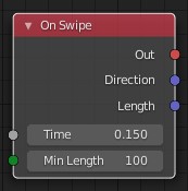
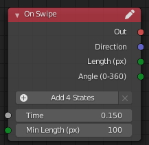
Time - duration of the swipe (default value 0.15 s);
Min Length - the minimum length that the swipe must “pass” (default value 100 px).
Output parameters:
Direction - normalized vector of the swipe direction;
Length - the length of the swipe (to assess the “strength”).
The Length output parameter is calculated by the vector value (without normalization) to relate to the input value.
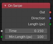
Very nice! It could fit very well into the Input category indeed.
The length socket probably should be a float socket as a float is returned and not a vector? Also, maybe you could change the label of the second input socket to Min Length (px) to be a bit more verbose.
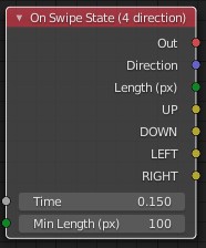
I’m waiting for a suggestion on the name, if anyone really needs it … Question: Do I need to output the angle (in the range from 0 to 360) to reduce the calculations to the user?
P.S. I plan to make a version with 8 directions (UP-LEFT, UP-RIGHT, DOWN-LEFT, DOWN-RIGHT).
It is also focused in mobile with these values in drop down box:
Started, Down, Released, Moved
Top Left, Top, Top Right
Left, Center, Right
Bottom Left, Bottom, Bottom Right
What do you think? The possibilities are:
Put a Started for Top Left and a Released for Bottom Right for example, and get a kind of swipe from the Top Left to the Bottom Right.
Double tap (or multi tap?) with the timer - or should i leave this to be done with other nodes?
I also am wondering about big possibilities:
Use different layouts (9 divisions like above, 4 divisions, 2 divisions horizontal or vertical) or it is unnecessary? Because the 9 divisions theoretically will have all these values.
Create a dead-zone (margin) and subdivisions thickness (too much math for not too much reasonable purpose i guess)
Takes different center places, for example, the scale can be changed and the layout can be placed in other place instead of the entire screen, acting like a “button” instead. But i don’t know what is the best approach to do that yet and maybe Canvas do a better job.
Unfortunately these possibilities will increase too much the node code and there is other better ways to that like Canvas, i am not sure about this. But the main node i mentioned i plan to make soon.
I suppose it’s better to make it a separate node, an event. I have no idea how to do this without a timer. It will not be difficult for me to do this. So you can leave this task to me.
What for? If the current solution works and this algorithm is used in other engines (it means that it has been tested in practice).
I think this is a very specific setting, do you know a lot of practical applications? The nodes must be created for use in real-world tasks. It would be possible to create a node with the setting of “cells” as tables (indicate the number of columns and rows, then such a “table” was automatically expanded), but in my case only 2 columns were needed.
You can create a node that, like a button from Canvas, will track a certain area, in this case, the advantage will be the presence of the “Down”, “Moved” state, since the Canvas does not have it, there is only Click (send event).
I can suggest creating a Drag-and-drop node - this is often used in games.
Maybe we can find one node usable for drag and drop and for a button.
One idea is: create a “box” using screen coords as its center and only add/subtract a value in both directions (x and y) where you want. Is this more light then buttons ?
Drag and drop is already possible, you just need to get the coords where the click started and where the click is released. If the click was not released where you want, just don’t do nothing. I just don’t know if you just “release” a button without “start” in there will work. If not, we will need to use that “box” coords.
Of the improvements, I plan to find a way to change the number of output parameters (like arrays for input values) in order to make one universal node.
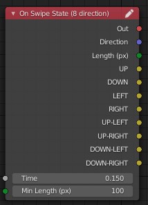
New version.
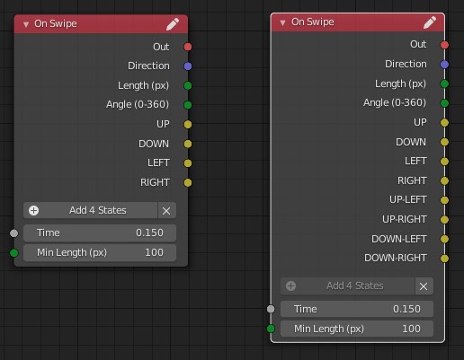
Single universal node for Swipe event:
Input parameters:
Time - duration of the swipe (default value 0.15 s);
Min Length (px) - the minimum length that the swipe must “pass” (default value 100 px).
Output parameters:
Direction - normalized vector of the swipe direction;
Length (px) - the length of the swipe (to assess the “strength”);
The Length output parameter is calculated by the vector value (without normalization) to relate to the input value.
Angle (0-360) - swipe angle in the range from 0 to 360 degrees (0 is on the right, i.e. Vector (1, 0) = 0 degrees).
States are states with direction output (Up, Down …). By default, they are not displayed, but if you press “Add 4 State”, then 4 states will appear (Up, Down, Left, Right - the left part) and if again, then 8 states will already be displayed (the right part).
Due to the fact that adding/removing occurs in 4 elements, I had to write classes/handlers in a Python script and register them there (regarding the ArmNodeAddOutputButton function I created an issue as there is a problem).
I first made the addition one at a time, but it’s more difficult to understand that if there are 5 output parameters, then a different direction determination algorithm is used (for 4 directions - 4 segments, 90 degrees each; for 8 directions - 8 segments, 45 degrees each).
Questions:
for the classes / handlers ArmNodeAddOutputButton and ArmNodeRemoveOutputButton (which are in the arm_nodes.py file) there is registration, but there is no “unregister_class” (I didn’t find it), so I also don’t know if I need to do “unregister_class” for my classes?
do the developers agree if such a “complex” description will be in the node or is it better to make it easier?
In my node I came across an error related to the output.
For Direction I used Vec3, but other nodes like Rotate Object or Aplly Force use Vec4 as input. For HTML5, Krom it is not critical and works. But for Android ( C ) an error occurs and the app crashes.
Will update the node.
Sorry, I didn’t think about such problems.
It would be nice to have a description of the required (required) data types for nodes.